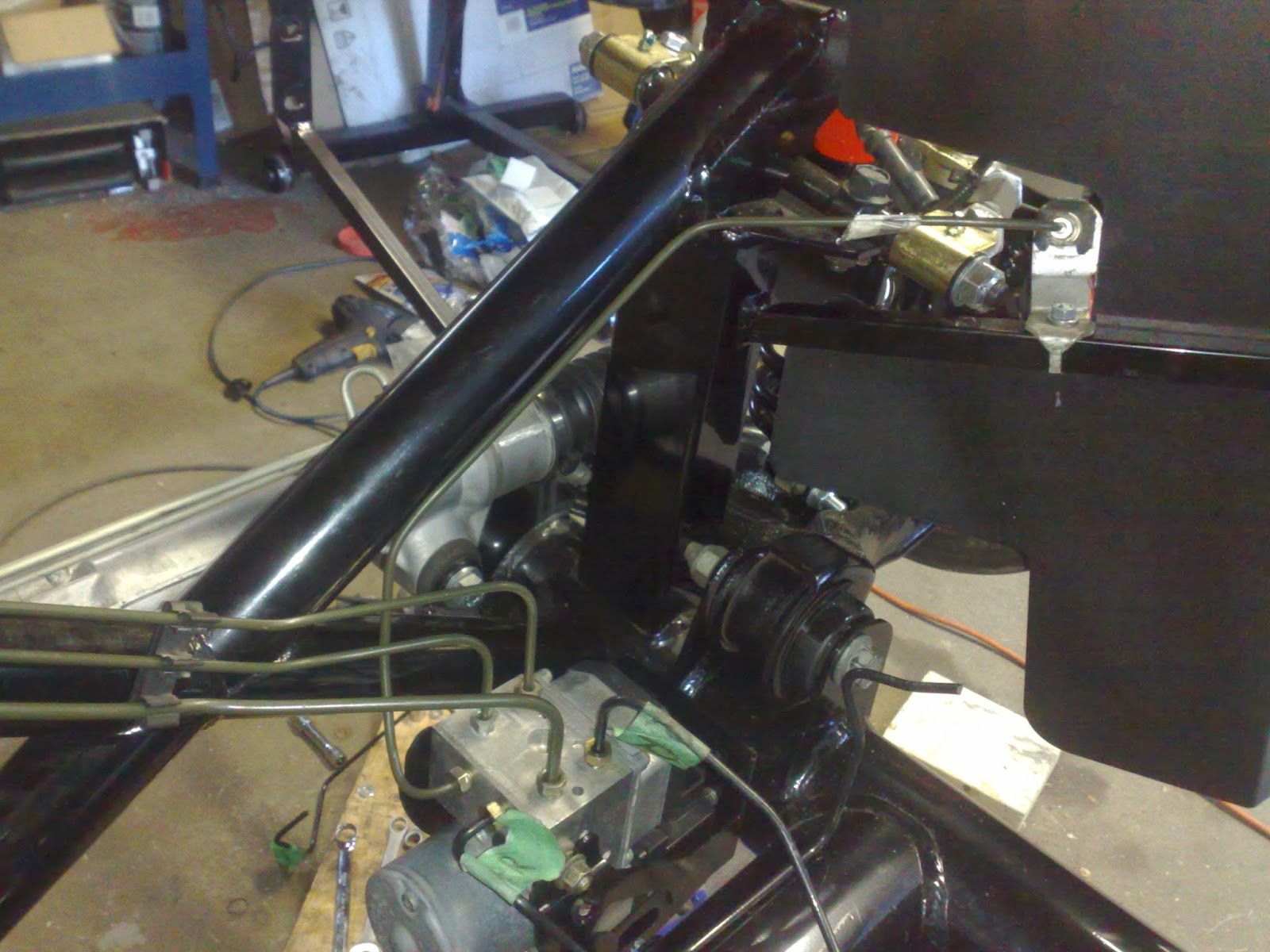
At this time I had the fuel lines positioned all the way up to the engine. I needed the engine dropped in to make sure I have the line ending at the right spot. This is where the adventure begins.
Before the engine goes in it needs to be "refreshed". The thing was in the mustang for over 10 years so it's not looking shiny enough for me. Moreover, the engine has to go through a series of small modifications to make it work in the new home.
The engine has spend the longest time on the stand now. It has collected some dust and needed a basic clean up job. I did not go overboard with this and gave up after a quick Simple Green MAX degreasing. It was good enough for me at this time. The next part was to get collectors off. They will be turned 180* to face forward to work with the side pipes. These things are not pretty by any means but apparently (and a bit sadly for me) are well designed and don't impede the flow. So no headers for me. I did, however, spend time to gasket match the ports on them.
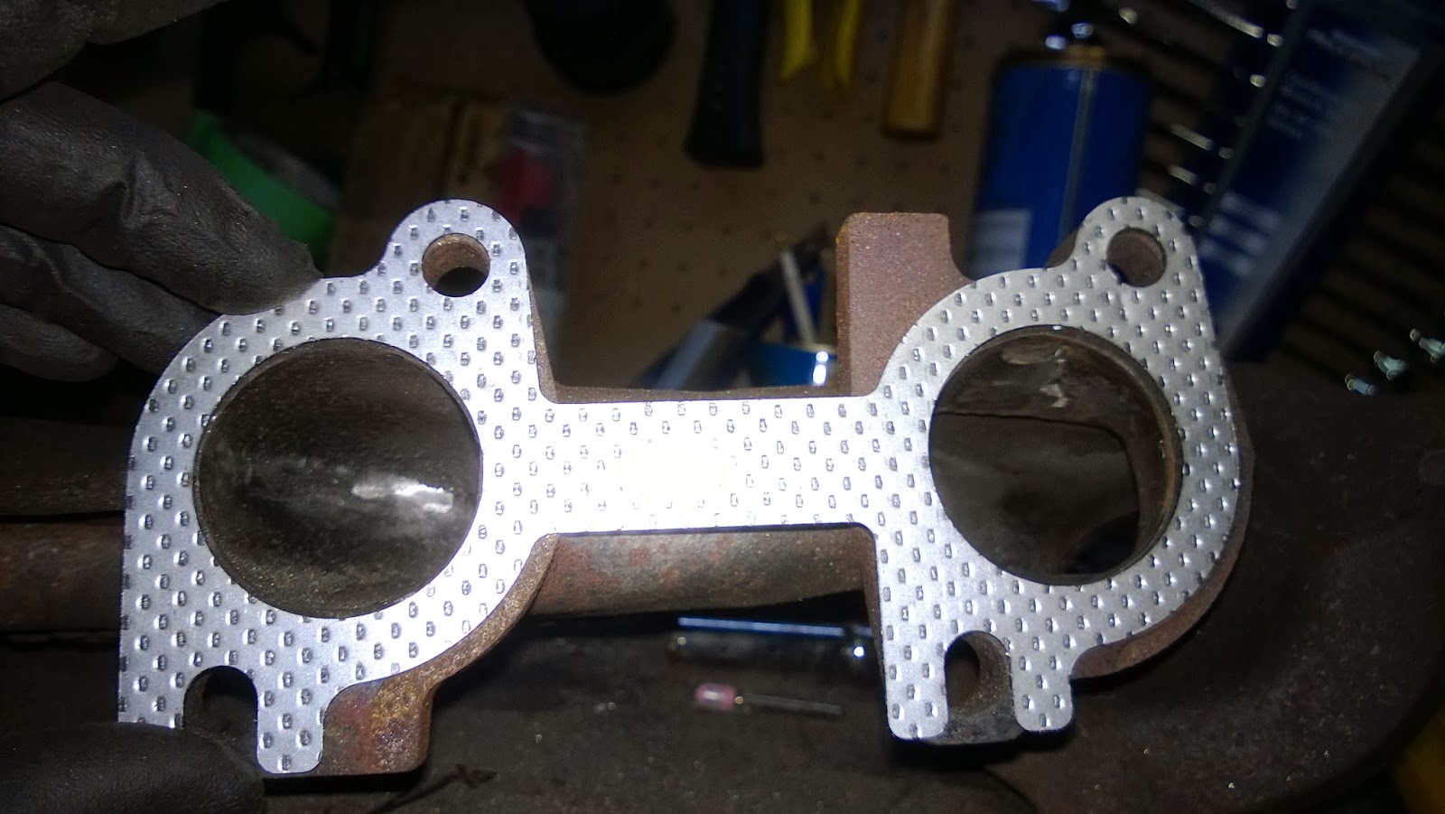
I also ensure that the inside is polished too. The casting left the surface full of mini bumps. It took me way too much time and effort to level it out and bore out the ports. It is cast iron after all. The things went significantly faster on the other side of the gasket. The heads are aluminum and are much softer. Here are some pictures of before. If you look close enough you'll notice that the gasket is about 1-2 mm larger than the port.
Here it's more obvious with the carbon deposit marks. See what happens when the gasket does not fully seal the exhaust system? The left port here exposes the blow by the gasket visible by the black deposits.
And now the "after"
Now that collectors needed some make over too
and now comes some header paint from VHT
While at it, the cats get the same treatment.
Ah, the things I do for my wife. These stupid things have a brick inside that chocks the exhaust system and robs me of the valuable horse power. But I have to make sure my loved one is not deafened by the roar of the V8. On the plus side, she cannot complain anymore that my cars are not environmentally friendly gas guzzlers. Maybe one day the turbos will replace these pesky catalytic converters. However, till that day comes they will be pretty.
Since I am on the painting spree, the engine block got a coat of VHT metallic paint
The trick is to use aluminum foil for masking. It's way easier than any kind of masking tape and paper. Here's the result.
It's not in your face colour popping paint job but I like it. While the engine mounts where off the block they too got sprayed.
I will take a break here and continue in a next post. The next little mods are a bit involved and deserve individual posts.
Saturday, March 1, 2014
Sunday, February 9, 2014
Give me fuel! give me .... anything but fire.
I was moving on to complete the fuel system. There were a few tasks remaining. One was to complete the filling neck. The second was to run the supply and evap lines to the engine. The strange thing is that I did not take any pictures making the filler neck. Therefore, I am not going to spend much time on it. It was basically cut at the right spot. Insert the hose between the two cut off parts. And have a cold one.
Of course, it was a bit more involved but really nothing to write home about.
The fuel lines were a bit more interesting. First of all, I did some planing. I am quite proud. I rarely do planning. Due to the location of the lines, the fuel filter could not be easily mounted. That was one of the reasons for the battery relocation box. That box will also act as a fuel filter support bracket.
I replaced the old mustang filter with the fresh one. I got this thing from Part Source and, unlike the old filter, it did not have the flow direction arrows. I had to put them on myself to avoid placing the filter on backwards.This location worked out really well. The hoses were not forced into place but maintained their original bends for most of the time. The hard fuel line was bent to work with this location of the filter and therefore worked perfectly.
Taking pictures from under the car with the light above does not work well.
Here you can see the thicker metal line routed along the brake lines. The hose is the evaporation line that I got from NAPA. Both, the supply fuel line and the evap line are running along with the brake lines. In fact, I used some of the funky mustang plastic mounts that hold all the lines together.
In order to know the required position of the fuel lines at the front I had to put the motor in to see where the lines should be.
At this time, it was just a dry run the motor would have to be pulled out later.
It was a good exercise and as you can see the perfect location for the fuel line was found. The supply line come up from under passenger foot box and goes up along the bend. This location actually moves the fuel line far enough from the exhaust manifold and the associated heat.
The evap line ends into some control valve. I did not want to expose the evap system unnecessarily and chose to hide it here.
It's actually right by the bottom of the passenger foot box, near the 4" frame tubing. Here you can see the fuel supply line come up too. The location for this purge valve looked good. I used some nutserts to mount the valve to the sheet aluminum.
From here on things went a bit sour. Too start, the picture above does not show starter motor. Once the starter motor was in placed the purge valve was awfully close to it. I haven't looked into that problem yet. My attention was concentrated on the fuel leak that was happening at the only custom made flare between the hard line and the hose that links to the engine.
My attempt to repair the flare only ruined the line further. The above pic clearly shows how the flaring tool slipped stripping the top level of metal. This resulted in a purchase of a 30" fuel line with the flares done on both ends at the factory. The new line was a bit too long. I would love to have something around 24-26".
The new line above is a bit long and had to curve to the front a bit. The tissue on the junctions is there to see if there are any new leaks. And there were sadly. I was not out of the woods yet. This time I could only blame the barb fitting. I was using the Factory Five supplied Edelmann fitting. Till now I have two theories, either the fitting was defective or it was damaged during my first installation against my hand made flare. I found it a bit challenging to find the fitting. I could easily order it form Summit racing but the shipping would cost me dearly. Luckly, I found out that WrenchMonkey had the fitting and would not cost me too too much for shipping. They are actually located very close and were able to deliver my part next business day. Once the fitting was replaced I was back on track with no more fuel leaks. However, all these fuel leaks had ruined my black rubber coating on the foot box. I'll have to fix that up one day. On the bright side, nothing caught fire. I have a video of the car cranking with fuel dripping and sparks flying but that's material for next posts. For now, I have bought one of these
Of course, it was a bit more involved but really nothing to write home about.
The fuel lines were a bit more interesting. First of all, I did some planing. I am quite proud. I rarely do planning. Due to the location of the lines, the fuel filter could not be easily mounted. That was one of the reasons for the battery relocation box. That box will also act as a fuel filter support bracket.
I replaced the old mustang filter with the fresh one. I got this thing from Part Source and, unlike the old filter, it did not have the flow direction arrows. I had to put them on myself to avoid placing the filter on backwards.This location worked out really well. The hoses were not forced into place but maintained their original bends for most of the time. The hard fuel line was bent to work with this location of the filter and therefore worked perfectly.
Taking pictures from under the car with the light above does not work well.
Here you can see the thicker metal line routed along the brake lines. The hose is the evaporation line that I got from NAPA. Both, the supply fuel line and the evap line are running along with the brake lines. In fact, I used some of the funky mustang plastic mounts that hold all the lines together.
In order to know the required position of the fuel lines at the front I had to put the motor in to see where the lines should be.
At this time, it was just a dry run the motor would have to be pulled out later.
It was a good exercise and as you can see the perfect location for the fuel line was found. The supply line come up from under passenger foot box and goes up along the bend. This location actually moves the fuel line far enough from the exhaust manifold and the associated heat.
The evap line ends into some control valve. I did not want to expose the evap system unnecessarily and chose to hide it here.
It's actually right by the bottom of the passenger foot box, near the 4" frame tubing. Here you can see the fuel supply line come up too. The location for this purge valve looked good. I used some nutserts to mount the valve to the sheet aluminum.
From here on things went a bit sour. Too start, the picture above does not show starter motor. Once the starter motor was in placed the purge valve was awfully close to it. I haven't looked into that problem yet. My attention was concentrated on the fuel leak that was happening at the only custom made flare between the hard line and the hose that links to the engine.
My attempt to repair the flare only ruined the line further. The above pic clearly shows how the flaring tool slipped stripping the top level of metal. This resulted in a purchase of a 30" fuel line with the flares done on both ends at the factory. The new line was a bit too long. I would love to have something around 24-26".
The new line above is a bit long and had to curve to the front a bit. The tissue on the junctions is there to see if there are any new leaks. And there were sadly. I was not out of the woods yet. This time I could only blame the barb fitting. I was using the Factory Five supplied Edelmann fitting. Till now I have two theories, either the fitting was defective or it was damaged during my first installation against my hand made flare. I found it a bit challenging to find the fitting. I could easily order it form Summit racing but the shipping would cost me dearly. Luckly, I found out that WrenchMonkey had the fitting and would not cost me too too much for shipping. They are actually located very close and were able to deliver my part next business day. Once the fitting was replaced I was back on track with no more fuel leaks. However, all these fuel leaks had ruined my black rubber coating on the foot box. I'll have to fix that up one day. On the bright side, nothing caught fire. I have a video of the car cranking with fuel dripping and sparks flying but that's material for next posts. For now, I have bought one of these
Thursday, January 9, 2014
Charcoal canister and say goodbye to gas smell
It's time to start on the fuel system. I kind of already did by installing the fuel tank earlier but there are more components to that system. One of them is charcoal canister. This thing acts as a filter for gas fumes. Actually, this component is part of evaporation control system but who cares about the semantics. Most custom cars would skip this entire system for the sake of simplicity. I'll install as much stuff as I can especially since the parts are on my shelf anyways.
Here's the beast:
First things first - cleaning it up. Then, we need to find the good location for it and mount it. The mounting bracket was designed for mustang and, therefore, needed some modifications to work on my car.
The changes include: cutting of the original mounting points, drilling new mounting holes and making that 1.25" hole for rerouted hoses. Of course, the bracket needs a fresh coat of rust paint.
The location is on the driver side under the rear fender. I did not have the aluminum installed there at the time yet. Thus, it was my next step. After some time I had this as the result
It was the time to bolt on the mount. It's held in position with three bolts and spaced out with 1/8" washers to avoid any rattling.
Here's the canister in position. The hose would come from behind throw the pre-cut hole with a grommet. The other hose was simply routed under the aluminum panel. You can barely spot them run behind the bend up flap on the fuel tank.
That's it. No gasoline smell is expected. I get bonus points for being environmentally friendly too.
Here's the beast:
First things first - cleaning it up. Then, we need to find the good location for it and mount it. The mounting bracket was designed for mustang and, therefore, needed some modifications to work on my car.
The changes include: cutting of the original mounting points, drilling new mounting holes and making that 1.25" hole for rerouted hoses. Of course, the bracket needs a fresh coat of rust paint.
The location is on the driver side under the rear fender. I did not have the aluminum installed there at the time yet. Thus, it was my next step. After some time I had this as the result
It was the time to bolt on the mount. It's held in position with three bolts and spaced out with 1/8" washers to avoid any rattling.
Here's the canister in position. The hose would come from behind throw the pre-cut hole with a grommet. The other hose was simply routed under the aluminum panel. You can barely spot them run behind the bend up flap on the fuel tank.
That's it. No gasoline smell is expected. I get bonus points for being environmentally friendly too.
Sunday, January 5, 2014
Brakes routing and plumbing.
The time has come to make sure that the snake will stop. It's not going far for now but let's hope for the best for later. The brakes need to be done rather early. The main reason is that running brake lines is much easier when there are less parts in the way.
The brake system is very primitive. We have one pedal that causes pressure in one the cylinder. In turn, this pressure causes the pistons in brake calipers to press brake pads against rotors. That is it! No magic here. In fact, that's exactly how Factory Five wants us to build brakes. That's what they have in the build manual. And that's how cars were build back in a day. Moreover, some new race cars are still build this way. As a matter of fact, NASCAR racers still have this setup. However, there has been some modernization done to the bare bone brake systems over the past 50+ years. Some of it is nice and some of it may be argued endlessly depending on various perspectives.
Let's start with simple stuff. Today cars have dual piston master cylinders. That part connected to the pedal. The main motivation is safety. Say you were unlucky and hit something big with the bottom of your car and one of your brake lines developed a small leak. This would be the end of your brakes normally. But if you have two cylinders, it would be only the end of the half of your brakes. :) You would still have one completely functional system that operates, usually, half of your car. Here's the modern car trick demystified. We have two cylinders. Each controls one front wheel and one diagonally opposite rear wheel. This adds some redundancy and increases safety.
The next major difference between older cars is the comfort. Today, most of the R&D goes into the refinement of the cars. We don't really see any new innovation in cars drive train. The story is very different when it comes to everything else: ride quality, interior finishes, electronics, etc. The brakes are on that list too. The major enhancement that was done is called "power brake" or "brake booster". The motivation was to make the actuation possible with least amount of effort from the driver. If you want to experience the "manual" brakes in your everyday car, just let it roll down the hill in neutral with out engine running and step on the brakes. (Be prepared to REALLY step on the brakes and if anybody asks: it was YOUR idea :))
Of course there must be the infamous ABS. I'm not even sure many people know what it is but they all want it anyway. This is where things turn 20th century. We have electronic sensors on each wheel connected to a computer that is controlling the brake pressure at individual wheel. The truth is I don't know exactly what witchcraft is happening inside this actuation box so let's just call it "the box of tricks". :)
One more thing that was recently added to the brakes is "traction control". Surprised? Well the reality is that cars loose traction when the driver has the right foot a bit too heavy. The brakes come to the rescue in such events. The computer on board, the same thing that controls ABS, applies the same witchcraft using the same "box of tricks" to, basically, apply the brakes. So, really, the traction control is just a piece of software that help us restrain those crazy drivers out there. Luckily for those crazy drivers, there's an override button :)
Enough with the theory. My plan is to retain all of the features mentioned above. The power brakes, ABS, traction control, all of it. There's a remote possibility my wife would want to drive this car. Let's eliminate as many excuses "not to drive" as possible.
Onto the mounting of the components. You have already seen the pedals. The thing on the other side is the master cylinder.
Notice that there are two metal lines are coming down from the dual master cylinder. There are also two bleeders with back rubber caps for bleeding each cylinder. The interesting part here is that the fluid reservoir is on the other side of the 3/4" tubing and would be inaccessible with the body on. Thus, the problem needs to be addressed but later. Now we need to mount that "box of tricks". I modified the mustang part and found a new home.
It was originally mounted like so but it turned out too low
Later I relocated it a bit higher but in the same spot. The bottom had to be inline with the frame. Here's the final assembly
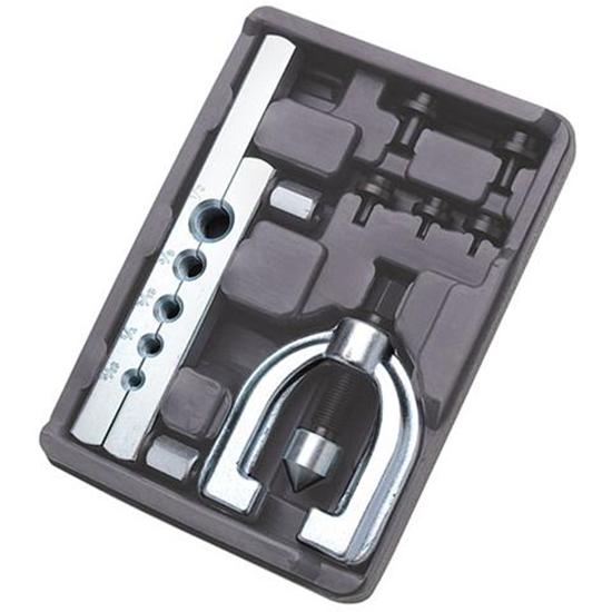
Now onto the fun part: connecting all the components together. This is usually done by running steel brake line between components. The lines need to have a perfect seal to withstand thousands of psi of pressure. To do so the lines are flared on each end and are pressed in place by end nuts. Since the lines are custom formed for each application some tools are required to complete the job. Here's what I've got.
The cheap flare tool. The reviews are true. It does suck.
And this bender. Tricky to use but no complains.
Here's what it all turned into
The start was the hardest but once I got the hang of it it was a blast.
The rear end got a bit busy but not tricky. I think it was harder to take the proper picture rather.
Now back to that reservoir accessibility problem. Do you remember these on the road?
Well that bad boy had the brake fluid reservoir mounted on firewall. That means I can do following using the parts form that car.
The only catch is that that car is out of the production for some years and the parts are not available anymore. So be friends with your local junk yard. ;)
Once the lines were all affixed to the frame the system had to be complete with those red shiny calipers.
And there you have it! I dragged my wife out to help me bleed the system. It took some time and effort but in the end the brakes are done and functional. The brake booster is not connected yet but it's in place. The same goes for ABS electronics. All the sensors are there but no wires yet. That's it for now.
The brake system is very primitive. We have one pedal that causes pressure in one the cylinder. In turn, this pressure causes the pistons in brake calipers to press brake pads against rotors. That is it! No magic here. In fact, that's exactly how Factory Five wants us to build brakes. That's what they have in the build manual. And that's how cars were build back in a day. Moreover, some new race cars are still build this way. As a matter of fact, NASCAR racers still have this setup. However, there has been some modernization done to the bare bone brake systems over the past 50+ years. Some of it is nice and some of it may be argued endlessly depending on various perspectives.
Let's start with simple stuff. Today cars have dual piston master cylinders. That part connected to the pedal. The main motivation is safety. Say you were unlucky and hit something big with the bottom of your car and one of your brake lines developed a small leak. This would be the end of your brakes normally. But if you have two cylinders, it would be only the end of the half of your brakes. :) You would still have one completely functional system that operates, usually, half of your car. Here's the modern car trick demystified. We have two cylinders. Each controls one front wheel and one diagonally opposite rear wheel. This adds some redundancy and increases safety.
The next major difference between older cars is the comfort. Today, most of the R&D goes into the refinement of the cars. We don't really see any new innovation in cars drive train. The story is very different when it comes to everything else: ride quality, interior finishes, electronics, etc. The brakes are on that list too. The major enhancement that was done is called "power brake" or "brake booster". The motivation was to make the actuation possible with least amount of effort from the driver. If you want to experience the "manual" brakes in your everyday car, just let it roll down the hill in neutral with out engine running and step on the brakes. (Be prepared to REALLY step on the brakes and if anybody asks: it was YOUR idea :))
Of course there must be the infamous ABS. I'm not even sure many people know what it is but they all want it anyway. This is where things turn 20th century. We have electronic sensors on each wheel connected to a computer that is controlling the brake pressure at individual wheel. The truth is I don't know exactly what witchcraft is happening inside this actuation box so let's just call it "the box of tricks". :)
One more thing that was recently added to the brakes is "traction control". Surprised? Well the reality is that cars loose traction when the driver has the right foot a bit too heavy. The brakes come to the rescue in such events. The computer on board, the same thing that controls ABS, applies the same witchcraft using the same "box of tricks" to, basically, apply the brakes. So, really, the traction control is just a piece of software that help us restrain those crazy drivers out there. Luckily for those crazy drivers, there's an override button :)
Enough with the theory. My plan is to retain all of the features mentioned above. The power brakes, ABS, traction control, all of it. There's a remote possibility my wife would want to drive this car. Let's eliminate as many excuses "not to drive" as possible.
Onto the mounting of the components. You have already seen the pedals. The thing on the other side is the master cylinder.
Notice that there are two metal lines are coming down from the dual master cylinder. There are also two bleeders with back rubber caps for bleeding each cylinder. The interesting part here is that the fluid reservoir is on the other side of the 3/4" tubing and would be inaccessible with the body on. Thus, the problem needs to be addressed but later. Now we need to mount that "box of tricks". I modified the mustang part and found a new home.
It was originally mounted like so but it turned out too low
Later I relocated it a bit higher but in the same spot. The bottom had to be inline with the frame. Here's the final assembly
The cheap flare tool. The reviews are true. It does suck.
And this bender. Tricky to use but no complains.
Here's what it all turned into
The start was the hardest but once I got the hang of it it was a blast.
The rear end got a bit busy but not tricky. I think it was harder to take the proper picture rather.
Now back to that reservoir accessibility problem. Do you remember these on the road?
Well that bad boy had the brake fluid reservoir mounted on firewall. That means I can do following using the parts form that car.
The only catch is that that car is out of the production for some years and the parts are not available anymore. So be friends with your local junk yard. ;)
Once the lines were all affixed to the frame the system had to be complete with those red shiny calipers.
And there you have it! I dragged my wife out to help me bleed the system. It took some time and effort but in the end the brakes are done and functional. The brake booster is not connected yet but it's in place. The same goes for ABS electronics. All the sensors are there but no wires yet. That's it for now.
Thursday, January 2, 2014
Coilovers are here!
I come home and find out a mail delivery notice. After a quick trip to the post office, I have this:
This is somewhat special delivery for many many reasons. Let's start with saying that I have ordered it about 3-4 months ago. I have no clue why it takes so long to ship a box of parts. It came from Whitby Motorsports. The people there were pleasant but it took forever to complete the order. They are the only vendor that works with Factory Five to supply all parts for Canadian customers. I really had no choice this time but I hope there will not be a second order.
Oh, the second reason is quite simple: it's coilovers! These shocks and springs have been tuned by Koni on their testing track, on Factory Five Roadster for Factory Five Roadster. My expectations of ride quality are high.
Obviously I would not waste time. A short while later:
Here you could actually see how the bottom is assembled. The trick here is to first bolt on the live axle mount to the shock and only then the the mount to the control arm. Otherwise, there would not be enough clearance for the bolt to pass through.
The rear was a walk in the park compared to the front. Take the parts. Add some nuts and bolts and there you have it.
When the snap rings came in, I installed them right in with out any problems. Remember to zip tie the springs to the seats. This would prevent them from becoming unseated in a highly improbable situation.
With the coil overs in, I still had one regret. If you noticed, my quad shocks are out from the rear end. They did not clear the spring on the coilover. With the stock mustang setup the spring would be situated on the trailing arm just before the axle and would not interfere. Well, I'll just have to figure out how to make this work but that would be later.
This is somewhat special delivery for many many reasons. Let's start with saying that I have ordered it about 3-4 months ago. I have no clue why it takes so long to ship a box of parts. It came from Whitby Motorsports. The people there were pleasant but it took forever to complete the order. They are the only vendor that works with Factory Five to supply all parts for Canadian customers. I really had no choice this time but I hope there will not be a second order.
Oh, the second reason is quite simple: it's coilovers! These shocks and springs have been tuned by Koni on their testing track, on Factory Five Roadster for Factory Five Roadster. My expectations of ride quality are high.
Obviously I would not waste time. A short while later:
And I noticed that the snap rings that retain the spring seats are not in the box. :( This brings me back to my endless communications with Whitby. However, it was less painful this time. They had the rings in stock and mailed them over acceptably quick. In the mean time, I went on to assemble the coilovers and proceeded with the installation.
I had a lot of the front suspension done but was missing the control arms. The arrival of coilovers took away all the guessing about required modifications to the stock mustang arms. Yes, I am using the stock ugly arms. It's part of my plan build now, upgrade later.
Nothing special really but clean.
And now painted and shiny.
The installations of the control arms is trivial: stick them in and tighten the bolts. The only thing i really had to "modify" was to drill 2 holes per arm. The trick here is to install the rear shock mount from the live axle into the spring seat recess in the control arm. I straightened out the small piece of metal that is intended to keep the mount from rotating around the single mounting bolt. In the original location, this piece would be going into the hole on the same plane as the mounting hole. In the new location, I had the hole drilled right in the spring seat and directly under the mount. It took a bit of some wiggling around to get the mounting bolt in the hole but it was not impossible. I should have taken a picture of the final product but I was so happy with it I forgot. Now the only piece missing from the puzzle was the spring and shock combo. After putting a small fight ...
the thing was bolted in.
Here you could actually see how the bottom is assembled. The trick here is to first bolt on the live axle mount to the shock and only then the the mount to the control arm. Otherwise, there would not be enough clearance for the bolt to pass through.
The rear was a walk in the park compared to the front. Take the parts. Add some nuts and bolts and there you have it.
When the snap rings came in, I installed them right in with out any problems. Remember to zip tie the springs to the seats. This would prevent them from becoming unseated in a highly improbable situation.
With the coil overs in, I still had one regret. If you noticed, my quad shocks are out from the rear end. They did not clear the spring on the coilover. With the stock mustang setup the spring would be situated on the trailing arm just before the axle and would not interfere. Well, I'll just have to figure out how to make this work but that would be later.
Subscribe to:
Posts (Atom)