It's time to start on the fuel system. I kind of already did by installing the fuel tank earlier but there are more components to that system. One of them is charcoal canister. This thing acts as a filter for gas fumes. Actually, this component is part of evaporation control system but who cares about the semantics. Most custom cars would skip this entire system for the sake of simplicity. I'll install as much stuff as I can especially since the parts are on my shelf anyways.
Here's the beast:
First things first - cleaning it up. Then, we need to find the good location for it and mount it. The mounting bracket was designed for mustang and, therefore, needed some modifications to work on my car.
The changes include: cutting of the original mounting points, drilling new mounting holes and making that 1.25" hole for rerouted hoses. Of course, the bracket needs a fresh coat of rust paint.
The location is on the driver side under the rear fender. I did not have the aluminum installed there at the time yet. Thus, it was my next step. After some time I had this as the result
It was the time to bolt on the mount. It's held in position with three bolts and spaced out with 1/8" washers to avoid any rattling.
Here's the canister in position. The hose would come from behind throw the pre-cut hole with a grommet. The other hose was simply routed under the aluminum panel. You can barely spot them run behind the bend up flap on the fuel tank.
That's it. No gasoline smell is expected. I get bonus points for being environmentally friendly too.
Thursday, January 9, 2014
Sunday, January 5, 2014
Brakes routing and plumbing.
The time has come to make sure that the snake will stop. It's not going far for now but let's hope for the best for later. The brakes need to be done rather early. The main reason is that running brake lines is much easier when there are less parts in the way.
The brake system is very primitive. We have one pedal that causes pressure in one the cylinder. In turn, this pressure causes the pistons in brake calipers to press brake pads against rotors. That is it! No magic here. In fact, that's exactly how Factory Five wants us to build brakes. That's what they have in the build manual. And that's how cars were build back in a day. Moreover, some new race cars are still build this way. As a matter of fact, NASCAR racers still have this setup. However, there has been some modernization done to the bare bone brake systems over the past 50+ years. Some of it is nice and some of it may be argued endlessly depending on various perspectives.
Let's start with simple stuff. Today cars have dual piston master cylinders. That part connected to the pedal. The main motivation is safety. Say you were unlucky and hit something big with the bottom of your car and one of your brake lines developed a small leak. This would be the end of your brakes normally. But if you have two cylinders, it would be only the end of the half of your brakes. :) You would still have one completely functional system that operates, usually, half of your car. Here's the modern car trick demystified. We have two cylinders. Each controls one front wheel and one diagonally opposite rear wheel. This adds some redundancy and increases safety.
The next major difference between older cars is the comfort. Today, most of the R&D goes into the refinement of the cars. We don't really see any new innovation in cars drive train. The story is very different when it comes to everything else: ride quality, interior finishes, electronics, etc. The brakes are on that list too. The major enhancement that was done is called "power brake" or "brake booster". The motivation was to make the actuation possible with least amount of effort from the driver. If you want to experience the "manual" brakes in your everyday car, just let it roll down the hill in neutral with out engine running and step on the brakes. (Be prepared to REALLY step on the brakes and if anybody asks: it was YOUR idea :))
Of course there must be the infamous ABS. I'm not even sure many people know what it is but they all want it anyway. This is where things turn 20th century. We have electronic sensors on each wheel connected to a computer that is controlling the brake pressure at individual wheel. The truth is I don't know exactly what witchcraft is happening inside this actuation box so let's just call it "the box of tricks". :)
One more thing that was recently added to the brakes is "traction control". Surprised? Well the reality is that cars loose traction when the driver has the right foot a bit too heavy. The brakes come to the rescue in such events. The computer on board, the same thing that controls ABS, applies the same witchcraft using the same "box of tricks" to, basically, apply the brakes. So, really, the traction control is just a piece of software that help us restrain those crazy drivers out there. Luckily for those crazy drivers, there's an override button :)
Enough with the theory. My plan is to retain all of the features mentioned above. The power brakes, ABS, traction control, all of it. There's a remote possibility my wife would want to drive this car. Let's eliminate as many excuses "not to drive" as possible.
Onto the mounting of the components. You have already seen the pedals. The thing on the other side is the master cylinder.
Notice that there are two metal lines are coming down from the dual master cylinder. There are also two bleeders with back rubber caps for bleeding each cylinder. The interesting part here is that the fluid reservoir is on the other side of the 3/4" tubing and would be inaccessible with the body on. Thus, the problem needs to be addressed but later. Now we need to mount that "box of tricks". I modified the mustang part and found a new home.
It was originally mounted like so but it turned out too low
Later I relocated it a bit higher but in the same spot. The bottom had to be inline with the frame. Here's the final assembly
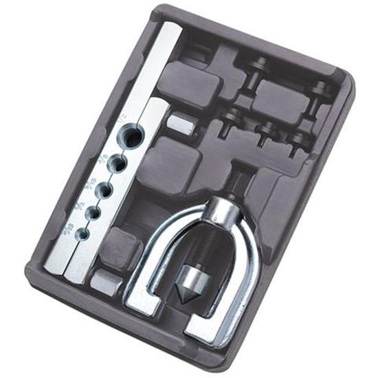
Now onto the fun part: connecting all the components together. This is usually done by running steel brake line between components. The lines need to have a perfect seal to withstand thousands of psi of pressure. To do so the lines are flared on each end and are pressed in place by end nuts. Since the lines are custom formed for each application some tools are required to complete the job. Here's what I've got.
The cheap flare tool. The reviews are true. It does suck.
And this bender. Tricky to use but no complains.
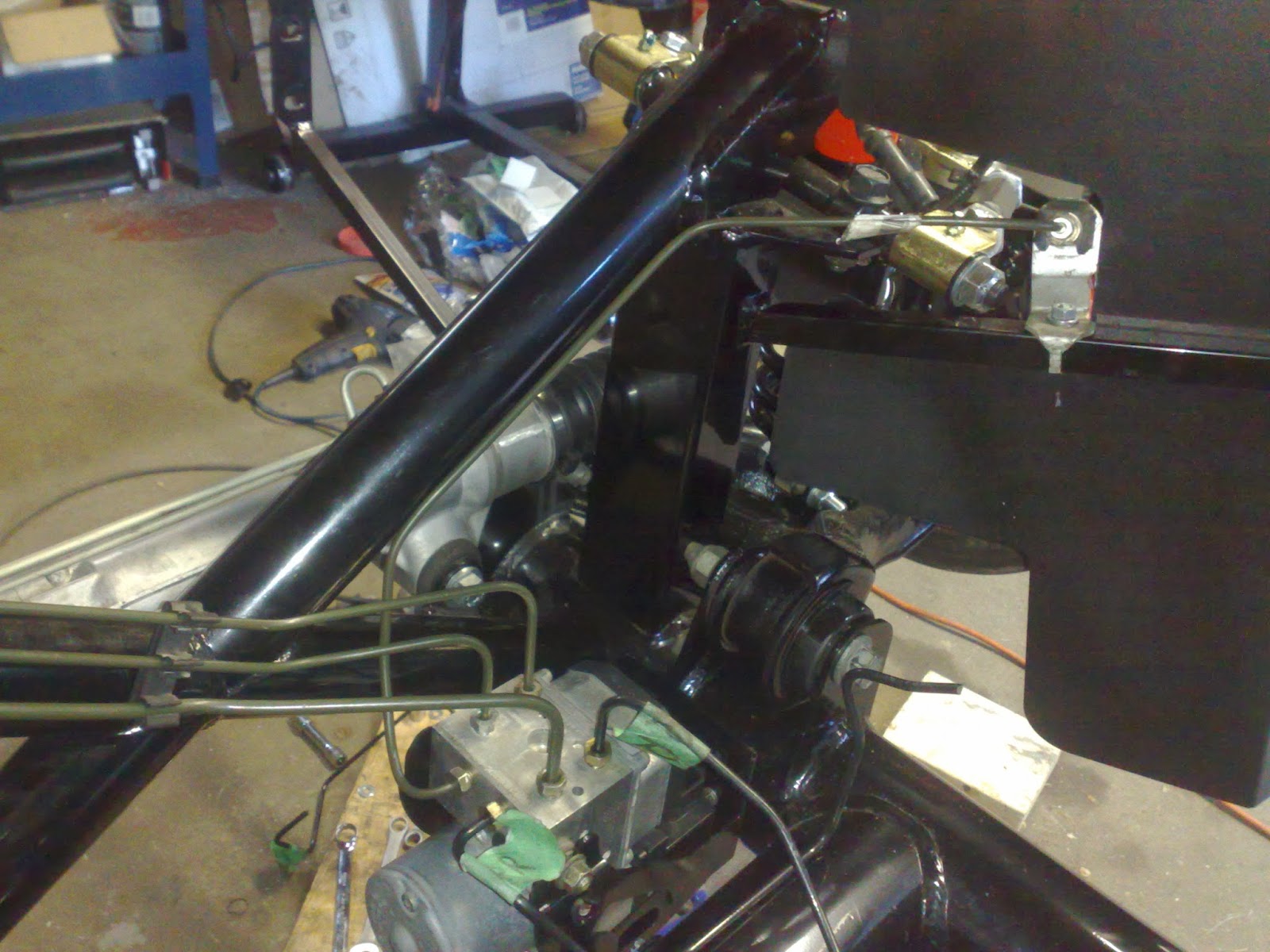
Here's what it all turned into
The start was the hardest but once I got the hang of it it was a blast.
The rear end got a bit busy but not tricky. I think it was harder to take the proper picture rather.
Now back to that reservoir accessibility problem. Do you remember these on the road?
Well that bad boy had the brake fluid reservoir mounted on firewall. That means I can do following using the parts form that car.
The only catch is that that car is out of the production for some years and the parts are not available anymore. So be friends with your local junk yard. ;)
Once the lines were all affixed to the frame the system had to be complete with those red shiny calipers.
And there you have it! I dragged my wife out to help me bleed the system. It took some time and effort but in the end the brakes are done and functional. The brake booster is not connected yet but it's in place. The same goes for ABS electronics. All the sensors are there but no wires yet. That's it for now.
The brake system is very primitive. We have one pedal that causes pressure in one the cylinder. In turn, this pressure causes the pistons in brake calipers to press brake pads against rotors. That is it! No magic here. In fact, that's exactly how Factory Five wants us to build brakes. That's what they have in the build manual. And that's how cars were build back in a day. Moreover, some new race cars are still build this way. As a matter of fact, NASCAR racers still have this setup. However, there has been some modernization done to the bare bone brake systems over the past 50+ years. Some of it is nice and some of it may be argued endlessly depending on various perspectives.
Let's start with simple stuff. Today cars have dual piston master cylinders. That part connected to the pedal. The main motivation is safety. Say you were unlucky and hit something big with the bottom of your car and one of your brake lines developed a small leak. This would be the end of your brakes normally. But if you have two cylinders, it would be only the end of the half of your brakes. :) You would still have one completely functional system that operates, usually, half of your car. Here's the modern car trick demystified. We have two cylinders. Each controls one front wheel and one diagonally opposite rear wheel. This adds some redundancy and increases safety.
The next major difference between older cars is the comfort. Today, most of the R&D goes into the refinement of the cars. We don't really see any new innovation in cars drive train. The story is very different when it comes to everything else: ride quality, interior finishes, electronics, etc. The brakes are on that list too. The major enhancement that was done is called "power brake" or "brake booster". The motivation was to make the actuation possible with least amount of effort from the driver. If you want to experience the "manual" brakes in your everyday car, just let it roll down the hill in neutral with out engine running and step on the brakes. (Be prepared to REALLY step on the brakes and if anybody asks: it was YOUR idea :))
Of course there must be the infamous ABS. I'm not even sure many people know what it is but they all want it anyway. This is where things turn 20th century. We have electronic sensors on each wheel connected to a computer that is controlling the brake pressure at individual wheel. The truth is I don't know exactly what witchcraft is happening inside this actuation box so let's just call it "the box of tricks". :)
One more thing that was recently added to the brakes is "traction control". Surprised? Well the reality is that cars loose traction when the driver has the right foot a bit too heavy. The brakes come to the rescue in such events. The computer on board, the same thing that controls ABS, applies the same witchcraft using the same "box of tricks" to, basically, apply the brakes. So, really, the traction control is just a piece of software that help us restrain those crazy drivers out there. Luckily for those crazy drivers, there's an override button :)
Enough with the theory. My plan is to retain all of the features mentioned above. The power brakes, ABS, traction control, all of it. There's a remote possibility my wife would want to drive this car. Let's eliminate as many excuses "not to drive" as possible.
Onto the mounting of the components. You have already seen the pedals. The thing on the other side is the master cylinder.
Notice that there are two metal lines are coming down from the dual master cylinder. There are also two bleeders with back rubber caps for bleeding each cylinder. The interesting part here is that the fluid reservoir is on the other side of the 3/4" tubing and would be inaccessible with the body on. Thus, the problem needs to be addressed but later. Now we need to mount that "box of tricks". I modified the mustang part and found a new home.
It was originally mounted like so but it turned out too low
Later I relocated it a bit higher but in the same spot. The bottom had to be inline with the frame. Here's the final assembly
The cheap flare tool. The reviews are true. It does suck.
And this bender. Tricky to use but no complains.
Here's what it all turned into
The start was the hardest but once I got the hang of it it was a blast.
The rear end got a bit busy but not tricky. I think it was harder to take the proper picture rather.
Now back to that reservoir accessibility problem. Do you remember these on the road?
Well that bad boy had the brake fluid reservoir mounted on firewall. That means I can do following using the parts form that car.
The only catch is that that car is out of the production for some years and the parts are not available anymore. So be friends with your local junk yard. ;)
Once the lines were all affixed to the frame the system had to be complete with those red shiny calipers.
And there you have it! I dragged my wife out to help me bleed the system. It took some time and effort but in the end the brakes are done and functional. The brake booster is not connected yet but it's in place. The same goes for ABS electronics. All the sensors are there but no wires yet. That's it for now.
Thursday, January 2, 2014
Coilovers are here!
I come home and find out a mail delivery notice. After a quick trip to the post office, I have this:
This is somewhat special delivery for many many reasons. Let's start with saying that I have ordered it about 3-4 months ago. I have no clue why it takes so long to ship a box of parts. It came from Whitby Motorsports. The people there were pleasant but it took forever to complete the order. They are the only vendor that works with Factory Five to supply all parts for Canadian customers. I really had no choice this time but I hope there will not be a second order.
Oh, the second reason is quite simple: it's coilovers! These shocks and springs have been tuned by Koni on their testing track, on Factory Five Roadster for Factory Five Roadster. My expectations of ride quality are high.
Obviously I would not waste time. A short while later:
Here you could actually see how the bottom is assembled. The trick here is to first bolt on the live axle mount to the shock and only then the the mount to the control arm. Otherwise, there would not be enough clearance for the bolt to pass through.
The rear was a walk in the park compared to the front. Take the parts. Add some nuts and bolts and there you have it.
When the snap rings came in, I installed them right in with out any problems. Remember to zip tie the springs to the seats. This would prevent them from becoming unseated in a highly improbable situation.
With the coil overs in, I still had one regret. If you noticed, my quad shocks are out from the rear end. They did not clear the spring on the coilover. With the stock mustang setup the spring would be situated on the trailing arm just before the axle and would not interfere. Well, I'll just have to figure out how to make this work but that would be later.
This is somewhat special delivery for many many reasons. Let's start with saying that I have ordered it about 3-4 months ago. I have no clue why it takes so long to ship a box of parts. It came from Whitby Motorsports. The people there were pleasant but it took forever to complete the order. They are the only vendor that works with Factory Five to supply all parts for Canadian customers. I really had no choice this time but I hope there will not be a second order.
Oh, the second reason is quite simple: it's coilovers! These shocks and springs have been tuned by Koni on their testing track, on Factory Five Roadster for Factory Five Roadster. My expectations of ride quality are high.
Obviously I would not waste time. A short while later:
And I noticed that the snap rings that retain the spring seats are not in the box. :( This brings me back to my endless communications with Whitby. However, it was less painful this time. They had the rings in stock and mailed them over acceptably quick. In the mean time, I went on to assemble the coilovers and proceeded with the installation.
I had a lot of the front suspension done but was missing the control arms. The arrival of coilovers took away all the guessing about required modifications to the stock mustang arms. Yes, I am using the stock ugly arms. It's part of my plan build now, upgrade later.
Nothing special really but clean.
And now painted and shiny.
The installations of the control arms is trivial: stick them in and tighten the bolts. The only thing i really had to "modify" was to drill 2 holes per arm. The trick here is to install the rear shock mount from the live axle into the spring seat recess in the control arm. I straightened out the small piece of metal that is intended to keep the mount from rotating around the single mounting bolt. In the original location, this piece would be going into the hole on the same plane as the mounting hole. In the new location, I had the hole drilled right in the spring seat and directly under the mount. It took a bit of some wiggling around to get the mounting bolt in the hole but it was not impossible. I should have taken a picture of the final product but I was so happy with it I forgot. Now the only piece missing from the puzzle was the spring and shock combo. After putting a small fight ...
the thing was bolted in.
Here you could actually see how the bottom is assembled. The trick here is to first bolt on the live axle mount to the shock and only then the the mount to the control arm. Otherwise, there would not be enough clearance for the bolt to pass through.
The rear was a walk in the park compared to the front. Take the parts. Add some nuts and bolts and there you have it.
When the snap rings came in, I installed them right in with out any problems. Remember to zip tie the springs to the seats. This would prevent them from becoming unseated in a highly improbable situation.
With the coil overs in, I still had one regret. If you noticed, my quad shocks are out from the rear end. They did not clear the spring on the coilover. With the stock mustang setup the spring would be situated on the trailing arm just before the axle and would not interfere. Well, I'll just have to figure out how to make this work but that would be later.
Wednesday, October 23, 2013
The heater endeavour
I've started to work on the sheet aluminium. Assembling foot boxes, I soon came to a realization that I need to have the firewall in place to continue further. It's no big deal really. There are two possible routs here. Take the firewall and rivet it in place. Alternatively, that is if you have a heater, pre-drill the firewall for heater and rivet it in place. Here's the catch: if heater is installed as per instructions the space that could normally be used for glove box would be completely consumed by the heater. In other words, there was a simple choice the heater or the glove box. I saw a few pictures of the dash with the glove box and think that the glove box is rather necessary, at least for the looks. This ultimately led to some modifications that could be done to regain some of the space for the glove box even with the heater installed.
My idea was simple and straight forward: push the heater further into the engine bay. After taking some measurements it was clear that about 2 inches could be had. The next step would be to prototype the solution to see how it would look like in real life. I used a cardboard box to design my modified firewall.
Here I outlined the firewall and placed the stencil for heater openings. The line at the bottom of the stencil is the location of 2x2 that holds the firewall. Thus, it's apparent that there is not much space below or above the heater.
My goal was to use the least amount of new sheet aluminum and reuse as much as possible. The motivation was simple: less cuts = less rivets = less work. Above you see that I literally split the new opening across at the center and bend it out. It gave me the desired depth for the heater and the leftovers made nice flaps for rivets.
This is the other piece that would make the extension complete. It would make up the back wall and the sides.
Here you can see the same stencil on the extension assembled. I had to provision some space on the sides and the top for the heater core to fit in. All in all it looked promising.
The next step is to try it out with the actual heater. Here, I have the heater core installed on the inside.
This is how it would look like from the other side. This is the passenger compartment side. The goal is to keep the side outlets as close as possible to the firewall (cardboard). I only have to provision some space for the ducting but that's really all I need there.
The next would be to see how it works on the car. So far looks promising.
Here's the other side. All systems go!
Some time later, with a bleeding finger, the parts were cut and bent. Notice this is not the design I had originally with cardboard. I actually missed some provisions with my prototype. The problem was mainly the missing flaps to join the bottom to the sides and the top to the sides. Here you see sides made separately with the top flap only. The back wall has the side flaps to join the sides. This part was done mainly to simplify my fabrication. What else you notice is the corner strips. I have came up with a clever approach to add rigidity to the firewall. The longer pieces would be running on the engine side along the firewall. They will join the sides and the firewall as well as overlap on the 2x2 vertically. The shorter pieces are going at the bottom corners and are joining the bottom to the side and too overlap the same 2x2 but horizontally. It would be more apparent once it all comes down as one assembly.
As with all of my aluminum parts, I sprayed the panels with rubberized coating to prevent oxidation.
The next step is to relax under a tree and rivet the pieces together. And voila!
Here's one more angle. You can see what I meant about those corner strips along the sides. Notice the two holes at the bottom. Those holes would be used to rivet the firewall to frame's 2x2 for rigidity.
My idea was simple and straight forward: push the heater further into the engine bay. After taking some measurements it was clear that about 2 inches could be had. The next step would be to prototype the solution to see how it would look like in real life. I used a cardboard box to design my modified firewall.
Here I outlined the firewall and placed the stencil for heater openings. The line at the bottom of the stencil is the location of 2x2 that holds the firewall. Thus, it's apparent that there is not much space below or above the heater.
My goal was to use the least amount of new sheet aluminum and reuse as much as possible. The motivation was simple: less cuts = less rivets = less work. Above you see that I literally split the new opening across at the center and bend it out. It gave me the desired depth for the heater and the leftovers made nice flaps for rivets.
This is the other piece that would make the extension complete. It would make up the back wall and the sides.
Here you can see the same stencil on the extension assembled. I had to provision some space on the sides and the top for the heater core to fit in. All in all it looked promising.
The next step is to try it out with the actual heater. Here, I have the heater core installed on the inside.
This is how it would look like from the other side. This is the passenger compartment side. The goal is to keep the side outlets as close as possible to the firewall (cardboard). I only have to provision some space for the ducting but that's really all I need there.
The next would be to see how it works on the car. So far looks promising.
Here's the other side. All systems go!
Some time later, with a bleeding finger, the parts were cut and bent. Notice this is not the design I had originally with cardboard. I actually missed some provisions with my prototype. The problem was mainly the missing flaps to join the bottom to the sides and the top to the sides. Here you see sides made separately with the top flap only. The back wall has the side flaps to join the sides. This part was done mainly to simplify my fabrication. What else you notice is the corner strips. I have came up with a clever approach to add rigidity to the firewall. The longer pieces would be running on the engine side along the firewall. They will join the sides and the firewall as well as overlap on the 2x2 vertically. The shorter pieces are going at the bottom corners and are joining the bottom to the side and too overlap the same 2x2 but horizontally. It would be more apparent once it all comes down as one assembly.
As with all of my aluminum parts, I sprayed the panels with rubberized coating to prevent oxidation.
The next step is to relax under a tree and rivet the pieces together. And voila!
Here's one more angle. You can see what I meant about those corner strips along the sides. Notice the two holes at the bottom. Those holes would be used to rivet the firewall to frame's 2x2 for rigidity.
Once in the firewall is in it's new permanent home, the heater was installed.
This is how it looks from the passenger compartment side. Here you can spot the shorter corner strips that lie on the top of the 2x2 and, again, add rigidity.
Mission is success!!! If I were to do it again: firstly, I'd rather not cut my finger with an angle grinder and, secondly, I'd add about a quarter inch of space to the sides and the top of the opening. The fit was a bit tight so the extra space would make the heater install step much smoother.
Wednesday, August 28, 2013
Cool! Let's do that 1200 times!
At this point I have a lot of things done. Wait, I am fooling myself. I have some things kind of taking their intended locations. The fact of the matter is that none of the suspension components are actually "done done". I am still waiting for my coilovers to come in from Whitby. It's taking way too long. It is only after the coilovers are fitted I can torque all the bolts and call the job complete.
In the meantime, I could work on the brakes but I am waiting for the pads to come in. It's not taking long but I am too lazy to go and and pick them up from TougeTuning. A friend of mine was planning on going there anyways and would grab my pads for me at the same time. Whenever that will be. There are a lot of the work involved with running the brake lines from the master cylinder to each wheel. But again, Whitby got the lines as part of the kit and are still not at my door step. :(
So while the parts are making their way, the real building can take place. A normal car these days is based on unibody design. That means that the frame is baked into the shell. The shell would have many other panels included. For example, firewall, floors, roof, etc. In my case, the frame is nothing more than just a frame and everything else comes separate. In fact, everything else is made of sheet aluminum panels which need to be installed together to form firewall, floors, etc.
Again, to prevent the oxidation and weakening of the aluminum I coated it with rubberized paint. Here's my paint booth, sort of:
The sun was of much help to me. I found out that the paint dries much faster in the sun, especially, being mate black. Each panel needs to be sprayed on the side that would not be otherwise covered. For instance, all the passenger compartment panels will be covered with sound deadening from the inside and don't need to be painted on that side.
The next steps are simple but laborious. First, the panel needs to be fitted to it's original spot. Then, I would trace all the supports with a sharpie. The panel is then removed and ready for mock up of the holes. The holes should be about two inches apart. I would measure the distance along one of the supports and do the math to figure out the even hole spacing. Once the holes are marked on the panel, I use a punch to ensure that drill bit does not wonder off. The next step is to drill the hole and clean the rough edges. Now the panel is ready for installation and would go back to the frame. This time I use clamps and self tapping screws to hold the panel in it's soon to be permanent position. I use the drill once again to drill the supports through the holes in the panel. The panel needs to come off one last time to allow for cleaning out the files. Also this is the time when I apply the silicone. I used Permatex clear silicone to prevent any noise from possible vibrations and to ensure that the joints are water tight. At this point the panel is ready for riveting.
In the meantime, I could work on the brakes but I am waiting for the pads to come in. It's not taking long but I am too lazy to go and and pick them up from TougeTuning. A friend of mine was planning on going there anyways and would grab my pads for me at the same time. Whenever that will be. There are a lot of the work involved with running the brake lines from the master cylinder to each wheel. But again, Whitby got the lines as part of the kit and are still not at my door step. :(
So while the parts are making their way, the real building can take place. A normal car these days is based on unibody design. That means that the frame is baked into the shell. The shell would have many other panels included. For example, firewall, floors, roof, etc. In my case, the frame is nothing more than just a frame and everything else comes separate. In fact, everything else is made of sheet aluminum panels which need to be installed together to form firewall, floors, etc.
Again, to prevent the oxidation and weakening of the aluminum I coated it with rubberized paint. Here's my paint booth, sort of:
The sun was of much help to me. I found out that the paint dries much faster in the sun, especially, being mate black. Each panel needs to be sprayed on the side that would not be otherwise covered. For instance, all the passenger compartment panels will be covered with sound deadening from the inside and don't need to be painted on that side.
The next steps are simple but laborious. First, the panel needs to be fitted to it's original spot. Then, I would trace all the supports with a sharpie. The panel is then removed and ready for mock up of the holes. The holes should be about two inches apart. I would measure the distance along one of the supports and do the math to figure out the even hole spacing. Once the holes are marked on the panel, I use a punch to ensure that drill bit does not wonder off. The next step is to drill the hole and clean the rough edges. Now the panel is ready for installation and would go back to the frame. This time I use clamps and self tapping screws to hold the panel in it's soon to be permanent position. I use the drill once again to drill the supports through the holes in the panel. The panel needs to come off one last time to allow for cleaning out the files. Also this is the time when I apply the silicone. I used Permatex clear silicone to prevent any noise from possible vibrations and to ensure that the joints are water tight. At this point the panel is ready for riveting.
Riveting is the easiest part of the job. It's kind of fun too unless the pin breaks loose and the rivet gun cannot take a grip on it. In such cases, it becomes a bit tricky but luckily it's does not happen often.
Here's the passenger foot box all done! There are in fact 1200 rivets in the supplied box. So I'd have to spend more time doing this. I did some rough math: say I spend 5 minutes on every rivet including measuring, drilling and gluing, that means I can only do 12 in an hour. Looking at the picture above you can see it takes a bit of time.
To tell the truth, I prepared a few more panels and thought that I would be able to complete the drivers side too but I realized that the firewall needs to be installed before the driver side foot box. Therefore, I need to figure out what to do with my heater which installs onto the firewall. Well, that's my next task then.
Subscribe to:
Posts (Atom)