Wednesday, October 23, 2013

The heater endeavour

I've started to work on the sheet aluminium. Assembling foot boxes, I soon came to a realization that I need to have the firewall in place to continue further. It's no big deal really. There are two possible routs here. Take the firewall and rivet it in place. Alternatively, that is if you have a heater, pre-drill the firewall for heater and rivet it in place. Here's the catch: if heater is installed as per instructions the space that could normally be used for glove box would be completely consumed by the heater. In other words, there was a simple choice the heater or the glove box. I saw a few pictures of the dash with the glove box and think that the glove box is rather necessary, at least for the looks. This ultimately led to some modifications that could be done to regain some of the space for the glove box even with the heater installed.

My idea was simple and straight forward: push the heater further into the engine bay. After taking some measurements it was clear that about 2 inches could be had. The next step would be to prototype the solution to see how it would look like in real life. I used a cardboard box to design my modified firewall.


Here I outlined the firewall and placed the stencil for heater openings. The line at the bottom of the stencil is the location of 2x2 that holds the firewall. Thus, it's apparent that there is not much space below or above the heater.


My goal was to use the least amount of new sheet aluminum and reuse as much as possible. The motivation was simple: less cuts = less rivets = less work. Above you see that I literally split the new opening across at the center and bend it out. It gave me the desired depth for the heater and the leftovers made nice flaps for rivets.


This is the other piece that would make the extension complete. It would make up the back wall and the sides.


Here you can see the same stencil on the extension assembled. I had to provision some space on the sides and the top for the heater core to fit in. All in all it looked promising.


The next step is to try it out with the actual heater. Here, I have the heater core installed on the inside.


This is how it would look like from the other side. This is the passenger compartment side. The goal is to keep the side outlets as close as possible to the firewall (cardboard). I only have to provision some space for the ducting but that's really all I need there.


The next would be to see how it works on the car. So far looks promising.


Here's the other side. All systems go!


Some time later, with a bleeding finger, the parts were cut and bent. Notice this is not the design I had originally with cardboard. I actually missed some provisions with my prototype. The problem was mainly the missing flaps to join the bottom to the sides and the top to the sides. Here you see sides made separately with the top flap only. The back wall has the side flaps to join the sides. This part was done mainly to simplify my fabrication. What else you notice is the corner strips. I have came up with a clever approach to add rigidity to the firewall. The longer pieces would be running on the engine side along the firewall. They will join the sides and the firewall as well as overlap on the 2x2 vertically. The shorter pieces are going at the bottom corners and are joining the bottom to the side and too overlap the same 2x2 but horizontally. It would be more apparent once it all comes down as one assembly.


As with all of my aluminum parts, I sprayed the panels with rubberized coating to prevent oxidation.


The next step is to relax under a tree and rivet the pieces together. And voila!


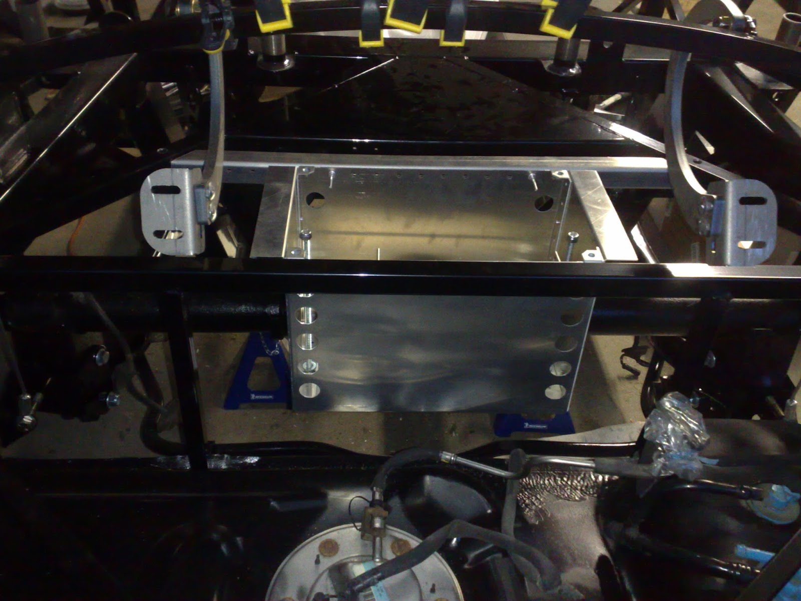
Here's one more angle. You can see what I meant about those corner strips along the sides. Notice the two holes at the bottom. Those holes would be used to rivet the firewall to frame's 2x2 for rigidity.


Once in the firewall is in it's new permanent home, the heater was installed. 


This is how it looks from the passenger compartment side. Here you can spot the shorter corner strips that lie on the top of the 2x2 and, again, add rigidity. 

Mission is success!!! If I were to do it again: firstly, I'd rather not cut my finger with an angle grinder and, secondly, I'd add about a quarter inch of space to the sides and the top of the opening. The fit was a bit tight so the extra space would make the heater install step much smoother. 

Wednesday, August 28, 2013

Cool! Let's do that 1200 times!

At this point I have a lot of things done. Wait, I am fooling myself. I have some things kind of taking their intended locations. The fact of the matter is that none of the suspension components are actually "done done". I am still waiting for my coilovers to come in from Whitby. It's taking way too long. It is only after the coilovers are fitted I can torque all the bolts and call the job complete.

In the meantime, I could work on the brakes but I am waiting for the pads to come in. It's not taking long but I am too lazy to go and and pick them up from TougeTuning. A friend of mine was planning on going there anyways and would grab my pads for me at the same time. Whenever that will be. There are a lot of the work involved with running the brake lines from the master cylinder to each wheel. But again, Whitby got the lines as part of the kit and are still not at my door step. :(

So while the parts are making their way, the real building can take place. A normal car these days is based on unibody design. That means that the frame is baked into the shell. The shell would have many other panels included. For example, firewall, floors, roof, etc. In my case, the frame is nothing more than just a frame and everything else comes separate. In fact, everything else is made of sheet aluminum panels which need to be installed together to form firewall, floors, etc.

Again, to prevent the oxidation and weakening of the aluminum I coated it with rubberized paint. Here's my paint booth, sort of:

The sun was of much help to me. I found out that the paint dries much faster in the sun, especially, being mate black. Each panel needs to be sprayed on the side that would not be otherwise covered. For instance, all the passenger compartment panels will be covered with sound deadening from the inside and don't need to be painted on that side.

The next steps are simple but laborious. First, the panel needs to be fitted to it's original spot. Then, I would trace all the supports with a sharpie. The panel is then removed and ready for mock up of the holes. The holes should be about two inches apart. I would measure the distance along one of the supports and do the math to figure out the even hole spacing. Once the holes are marked on the panel, I use a punch to ensure that drill bit does not wonder off. The next step is to drill the hole and clean the rough edges. Now the panel is ready for installation and would go back to the frame. This time I use clamps and self tapping screws to hold the panel in it's soon to be permanent position. I use the drill once again to drill the supports through the holes in the panel. The panel needs to come off one last time to allow for cleaning out the files. Also this is the time when I apply the silicone. I used Permatex clear silicone to prevent any noise from possible vibrations and to ensure that the joints are water tight. At this point the panel is ready for riveting.


Riveting is the easiest part of the job. It's kind of fun too unless the pin breaks loose and the rivet gun cannot take a grip on it. In such cases, it becomes a bit tricky but luckily it's does not happen often. 


Here's the passenger foot box all done! There are in fact 1200 rivets in the supplied box. So I'd have to spend more time doing this. I did some rough math: say I spend 5 minutes on every rivet including measuring, drilling and gluing, that means I can only do 12 in an hour. Looking at the picture above you can see it takes a bit of time. 

To tell the truth, I prepared a few more panels and thought that I would be able to complete the drivers side too but I realized that the firewall needs to be installed before the driver side foot box. Therefore, I need to figure out what to do with my heater which installs onto the firewall. Well, that's my next task then. 

Wednesday, August 14, 2013

Driver's controls

Once the steering rack is in, the next sensible thing to do is to put on the steering column. At least, so I thought. According to the assembly manual the order of event's should have been reversed. I did not check that until it was too late. :)

The problem with installing steering column was very simple: the steering rack connecting bit would be sticking out too far leaving not enough room to slide the column on. According to the manual, I was to install the column first and then swing the rack in with the driver side connected before installing.

Let's keep it in order. Firstly I needed to put the aluminum panel on. I choose to coat my aluminum with rubberized black paint. That meant that the panel would need be sprayed a day in advance to allow the paint to dry.


Notice that Factory Five does include the little fill plate that is just to the top right of the big bottom opening. It would be perfect time to put this plate on. I simply glued it in with silicon. The main panel was siliconed and riveted in place.   

I did not want to undo the rack so ended up wiggling the column on. It would not go in without a fight, but with a bit of authority, it clicked in :)

The next step is to install driver's pedals:


The donor parts would need to be modified here. The mounting bracket is removed from the pedals. This mod would allow the pedals to sit deeper in the foot well. Also, the angling bracket from hydroboost was removed and another spacer was placed into that spot. This is a critical combination of changes. The end result should have the distance from the brake pedal to the brake booster exactly the same as it used to be on the Mustang.

The gas pedal had to go through a series of adjustments. Both ends needed to be trimmed. The pedal part needs to be moved up and straightened. The top part did not require the adjustment but I trimmed it anyways since the bottom part was shortened. We have some basic physics here: the shorter the bottom part the less foot action is required. This effectively results in drastic throttle actuation with a small foot movement. That's why I cut off just over half an inch from the top too. Frankly, this pedal does not look promising. The fact that guys over at ffcars.com don't believe in it at all does not add any hope either. I'd just have to live to see it in action.


However form this angle, it does not look bad at all. Perhaps I am wrong about it...

Thursday, August 8, 2013

Steering rack

It's time to put on some parts that make the collection of parts a drive-able car. First step is the steering rack. The rack comes from the Mustang but needs to be adjusted. The front track of cobra is not as wide as Mustang's. This means that the inner tie rods would need replaced with shorter equivalents. There's also a variation in suspension geometry that creates need for some steering rack extensions. Now, it's time to make it happen. The steering rack's boots must come off to expose the inner tie rods.


I could not find a tool in my garage big enough to take the nut off. I had to make a trip to local Canadian Tire. I got one of these

I don't know how I lived without it. That thing is amazing! Probably one of the best $$$ I've spent on tools. Now armed with my new tool (and a piece of pipe of extra torque :) ), I took off the tie rods. Here's the comparison of old and new parts:


The left is the Mustang original. You can also see the adapter at the end of the right rod. It effectively moves the point where rods bend.

The rest was simple. The parts come together the same way they came off. I had some stainless steel zip ties left overs that I used for boot clamps.


For some reason the original Mustang tie rod ends did not work with the new inner tie rods. But Factory Five included a set of new ones.

I need that red button: "That was easy".

Saturday, August 3, 2013

Yey, first mod!

Friends don't let friends drive stock! I don't know what "stock" is for a custom car however. Anyways, here's what I got in mail:


This is a battery relocation kit from FFMetal.

Let's look at the problem first. The shape of the rear of car and the fact that the gas tank is in the rear contribute to a very small space left over for the trunk. The roll bar loops that you see behind the seats also have one support bar that extends diagonally and into the frame. Insistently, that is too cutting into the trunk space. To take the matters to the next level, the original location of the battery is in the trunk. By now you are probably thinking that the trunk is a busy area. Well, Factory Five did not stop on that yet. In my version of the kit the floor of the trunk is not curved around the fuel tank. What that means is that I get even less space. However, I do want to buy a soft top for this car and be able to store it in the trunk when it's not required. Therefore, the trunk space is a highly sought after commodity. Hence the battery relocation kit you see above.

The idea behind the kit is to move the battery out of the trunk and under the floor. There's actually just enough space between the gas tank and the live axle. Here's how that kit would fit:


There is a small detail here to pay attention too. The battery box must be away from the supports that carry gas tank. In the event of rear end collision the gas tank will swing inwards and should not be restricted. Notice that the box is designed to be just deep enough to hover on top of the gas tank in such event. Frankly, I am very impressed with Linwood's thoughtfulness and workmanship at FFMetal. I did have to trim the support bar slightly to make it fit, however. It was just a minor adjustment.

So with the box mocked up, I drilled all the holes for rivets on the chassis. I also installed the remaining rivets on the box its-self. There were only a few installed out of the packaging to make it keep its shape. Here's the final spot check before it hits the paint


All is looking good so we are off to spray it. This box is made of bear aluminum. Aluminium will oxidize overtime and form a protective layer on the surface. However, that weakens the metal. So I chose to coat my aluminium with Rocker Guard


And now here's how it looks installed to the chassis.


But it's not over yet. There's one more thing to do: cutting the opening in the floor. The floor needs to be positioned exactly as if it were installed. I used the clamps to temperately affix to the square tubing. The next step was to mark the area, drill the corners and cut the sides.


You'll notice that the cut out is actually bigger then the inside of the box. The idea was to let the lid sit flat with the floor. There is enough material on the box' sides and square tubing to allow for the rivets to be shifted outwards. Here's the how it looks with the lid on.


Great! The only new minor setback is that the battery I've got from Mustang does not fit into that box. :( I'd have to buy a new one that fits. I also need to put master disconnect switch and battery terminal relocation kit on to complete the setup. The battery is much less accessible in such location and would require those extras to make life easier and safer. All in all: mission accomplished!

Taking it apart

The next step is to actually take some parts off. The car comes with the a large quantity of aluminium panels attached to the chassis with temporary screws. The idea is to cut down on packaging, help the consumer to know where panels should go and ensure that the panels actually fit. I took some pictures for my reference. They should come in handy later on during assembly.


This kind of gives you an idea of what it looks like. The task at hand is to take it apart. This time I needed help from my wife. The panels had to be properly labeled. After all, I do have to put them back together again. My hand writing would only add to the challenge. Look above, there are neat and descriptive labels. A big thanks goes out to her for her efforts. Notice there are even small labels on the overlaps. Those indicate which panel overlaps which.

Well the rest was easy: take all the screws out and things would fall apart. The garage doors were closed so my wife could not run away easily. So she agreed to put in some elbow grease.


The dis-assembly took us only few minutes. All the panels were off and are on the shelf and the bare bones of Cobra were exposed:


Strangely, it is only at the time of writing I realized how many parts are missing from the car and how much is to be done.

Thursday, June 20, 2013

The fuel tank

I haven't been keeping up my writing but that does not mean that there's no progress. I haven't been contributing too many hours with so many other summer distractions. However, I am impressed with my work so far.

First of all, I continued with the "getting parts out of my way" strategy. The gas tank is rather a big part. It was up next. The procedure is already well established: dissemble, clean, rust paint, assemble, install.


It was almost be too easy. Of course, there had to be some deviation from the plan:


That's the filler neck seal on the gas tank. It dried up good and cracked. While I was removing it, the part almost separated into two. A quick call to Ford Parts department confirmed that they still overcharge. I had to order the part from the local Part Source for much less but with a couple of days wait. Apparently, it is a common problem with Mustangs. Usually, people notice the gas smell as the symptom. Here's the new part:


The other tricky step was the actual mounting. The gas tank has some folds of the pinch weld. Those folds are done to accommodate the Mustang mounting location. Factory Five, however, uses the pinch weld edges for mounting. Some elbow grease and pliers had to be employed to get the tank in. 

I left the job half done. I still have to put the evap lines back on. The charcoal canister is still on the shelf. I also got a new fuel filter but could not find a nice spot to mount it yet. In fact, I was planning on getting a battery relocation kit which would be mounted in the same area. It would make sense to route the fuel lines and mount the filter once other parts are in place. 


Sunday, May 5, 2013

Time is money

A few years back, just when I was starting on planing this project, I met a guy on the street driving a Cobra. I jump up and down and waived at him to pull over. He did and we chatted. I remember he was suggesting to go "all new parts" route instead of "donor" build. I remember a the time I thought, it's just way too much money to buy all new parts at retail prices. I still maintain that opinion but I have more to say. I am sure, I read it on FFCars too. Essentially, it comes down to what you have at your disposal: time or money. Here's my example to illustrate the concept.

I started my assembly from the part that was the most "in my way" in my garage. Well, the engine is really the  biggest obstruction but it's not going in just yet. However, the rear axle was lying with it's arms sticking out and constantly being the tripping hazard leaving painful scratches. The time has come for that thing to move into its new home. Of course, I could just grab it and bolt it in as is but it just would not look right. The dirt and dust covered part attached to a shiny glossy black frame. In addition, the Mustang was over 10 years old and needed some help in preventing future rusting. So some prep work was in order. I somehow ended up using Rust Check products. They are readily available at the local Canadian Tire and have an extensive variety of rust prevention products. They are a Canadian company with a convincing claim. I just hope that their claims are true.

The rear axle is only one of many bits that make up the rear end. In fact, the axle is probably an incorrect reference. To prepare the parts I need to clean, wire brush, degrease and paint them. So if I want to achieve a good result I would need to prep individual parts as much as possible. That means that I had to disassemble first. I took off all the obvious parts: linking arms, sway bar, anti squeal brackets, vibration dumper and brake shields. I could continue on with brake mounting brackets, hubs, etc ... but I had to stop somewhere. As I was taking the parts off, I was getting them done too. Here, for example, is the lower arms before and after wire brushing.


And here the same arm but now painted.


In the end that's what the rear axle looked like before I started to brash it. As you can see, there're some surface rust there. The axle looked pristine before I cleaned it. 


Here the same axle after I took a grinder with brush wheel to it.


Here I have to reveal my secret. Since there was some considerable surface rust, I elected to apply some Rust Converter. Well, I really did not see any colour change as shown on the label but I assumed it did its trick. The next step, before any painting is degreasing. I found Dupli-Color surface prep at Canadian Tire. I applied that liberally with a clean cloth. Once that's all dried up, the last step is to spray paint it. My choice was Rust Paint in glossy black. It looks good and protects the metal too.


Once it's all dried up it's ready to go. You probably guessed it takes an hour or two to get to this point. Alternatively, I could get a new axle and skip straight to this point. That's probably what everyone is talking about. The time invested into the prep could be saved and the build could be sped up by the use of new parts. In addition, Factory Five and some other shops offer some attractive alternatives to Mustang donor parts. But I am not complaining. It's fun in its own way to spray paint the parts.


Here the axle is in its new home. The advantage of using donor parts here is that sway bar. Other options use tubular lower arms and loose the sway bar. Life will show if that sway bar does more good than bad.

Sunday, April 28, 2013

Shedding skin

Now with the inventory sort of complete I get on to the real fun stuff. Let's put the car together. Ironically, the first step is actually to take the car apart. The fiber glass body must come off and then all of the aluminum panels should head to the shelves. The only problem is that the body is one piece that does not fit on the shelf nicely. So we need a body buck! The manual actually has some drawing and measurements for building one out of plywood and 2x4s. Also the guys over at FFCars have some advice. I had some 2x4s that were intended but not used for the pick up trip and some plywood that was left over from under the mustang shell. All I was missing was my in-law. He was the best pick for the job for two reasons: (1) he is a strong man and will help me lift the body off the frame, (2) he has a jig saw. :) Well, he showed up with jig saw and a bunch of other tools as well as a case of assorted screws. After a short while we saw this


We moved the body to the outside and rested it on the cardboard. Even though the drawings from the manual and the revised rear part from the forum where close to the actual shape of the car, they were not exact. It was no obstetrical


The problem was addressed with a smile. The buck was relativity simple to build and I had just the spot to hide the snakes skin.


It fits there amazingly well! It really appears as if that spot was meant for it. Although, Factory Five assures that the body is resistant to the elements and would be perfectly fine if stored outside uncovered, I would sleep better knowing that it's protected from harsh Canadian snow.

Some blue tarpaulin, some left over vapor barrier plastic, some tuck tape and voila! I hope raccoon don't make it their home. Oh and don't mind those parts on the tree. Didn't you hear of organic swaybars? Well now you know where they come from.